
How electrical heat tracing protects pipes from freezing
Electrical heat tracing protects pipes from freezing by replacing heat that escapes from the pipe and its contents into colder surroundings. An electrical heating cable runs along the pipe, while thermal insulation slows heat loss. Temperature controls switch or regulate the heat so that the fluid and pipe remain above a selected minimum temperature.
The cable does not have to make the pipe hot to the touch. Its job is to supply enough heat at the coldest expected conditions, including at valves, supports, and other points where heat escapes more quickly. Effective freeze protection depends on the cable, insulation, controls, and power supply working together.
The heat balance along a pipe
Heat naturally moves from a warmer pipe toward colder air. The greater the temperature difference, the faster heat is lost, all else being equal. Pipe diameter, insulation thickness and condition, wind exposure, and the length of the exposed run also affect the heat requirement. A long outdoor line with wet insulation can lose substantially more heat than a sheltered line with dry insulation of the same nominal thickness.
Electrical heat tracing offsets that loss through resistance heating. Current passing through the heating element generates heat, which transfers through the cable jacket into the pipe wall and then into the contents. Insulation surrounds the heated assembly to reduce the rate at which that energy escapes.
For a system designed to maintain a minimum temperature, the selected cable output at the relevant operating temperature must cover the calculated heat loss, including allowances used in the design. A cable's output rating alone is not proof of protection: output changes with temperature for some cable types, while fittings and installation details can increase local heat loss.
Freeze protection is also different from heating a cold system back to operating temperature. A tracing circuit sized to maintain a stationary liquid above its freezing point may take a long time to warm a pipe that has already cooled, or it may not meet a required heat-up time. Those are separate design conditions.
Heating cable types and their behavior
Two common choices for pipe freeze protection are self-regulating and constant-wattage heating cables. Both convert electricity into heat, but they respond differently as pipe temperature changes.
Self-regulating cable
A self-regulating cable has a conductive heating core between two parallel conductors. Its heat output generally decreases as its temperature rises and increases as it cools. This response occurs along the cable, so a colder section exposed to wind can produce more heat than a warmer section on the same circuit.
Self-regulation does not make temperature control or correct sizing unnecessary. The cable still requires a suitable circuit design, electrical protection, approved connection components, and a controller where specified. Its output must be evaluated at the intended pipe temperature and supply voltage, rather than assumed from a single nominal rating.
Constant-wattage cable
Constant-wattage cable delivers a more nearly fixed heat output for a given supply voltage. It can be useful where a predictable output is required, but it does not automatically reduce heat in warmer sections in the same way as a self-regulating cable. Controls and installation arrangements must therefore prevent temperatures from exceeding the limits of the cable, pipe, insulation, or process material.
Some heating cables can be cut to length in the field within their design limits; others have fixed lengths or defined cutting intervals. Overlapping rules also vary by product. The installation instructions for the selected cable determine how it can be routed and terminated.
Why insulation is part of the heating system
A trace-heated pipe without effective insulation can lose heat faster than the cable supplies it. Insulation reduces that loss; the heating cable compensates for the heat that still escapes. Increasing cable output cannot reliably correct an insulation system that is missing, damaged, or repeatedly saturated.
Wet insulation is a particular concern because moisture can reduce thermal performance and create a path for heat to escape. Outdoor insulation therefore needs suitable weather protection, with attention to joints, penetrations, valve covers, and the ends of removable insulation sections. Damage around a pipe support can expose a short cold section even when the rest of the line appears sound.
The insulation design must match the assumed pipe size, material, thickness, and exposure. If a pipe is insulated less heavily than the heat-loss calculation assumes, the installed tracing may be undersized. Conversely, changing insulation or cladding after installation can conceal damage to the cable or temperature sensor, so the final assembly matters as much as the original calculation.
Cold spots occur at more than the pipe wall
A straight length of pipe is relatively predictable. Valves, flanges, strainers, pumps, and supports introduce extra metal and surface area that draw heat away from the traced pipe. A pipe shoe connected to structural steel can conduct heat into the support, creating a local cold spot even when adjacent pipe temperatures are acceptable.
These features need to be included in the heat-loss assessment and cable layout. Additional cable is often routed around fittings or supports where the cable manufacturer's instructions permit it. Removable insulation covers can provide access for maintenance, but they must fit back closely enough to restore thermal protection after the work is complete.
Small-bore branches and dead legs deserve attention because stagnant liquid does not receive the same warming effect as fluid flowing from a heated upstream process. A drain line that is opened only occasionally can freeze while the main line remains above the freezing point. Instruments, impulse lines, and low points should be considered as parts of the system when they contain liquid exposed to cold conditions.
Flow conditions change the picture. Moving fluid can carry heat into an exposed section, whereas a shutdown leaves the trace heating system to maintain the pipe and stationary contents. The design condition should reflect the expected outage or idle state, not just normal production.
Temperature control and sensor placement
A thermostat or electronic controller uses a temperature measurement to switch or regulate the heating circuit. Ambient-sensing control responds to surrounding air temperature; pipe-sensing control responds to a sensor attached to the pipe. The appropriate approach depends on the process, the expected exposure along the circuit, and the required degree of temperature control.
Ambient control can energize tracing before pipework becomes cold, but air temperature alone does not reveal the actual pipe temperature. A pipe sensor measures the surface at its location, yet that location may not represent the coldest point on a long or unevenly exposed run. A sensor placed near a warm vessel, for example, can indicate adequate temperature while a distant outdoor branch is cooling.
Sensor attachment and insulation coverage affect the reading. The sensor should be installed as specified for the control system, with good contact where pipe temperature is being measured. Its position should also avoid being unduly influenced by direct contact with the heating cable unless the design calls for that arrangement.
The control setpoint needs a margin above the temperature at which protection is required, taking account of sensor placement, control response, and fluid properties. Water is not the only relevant fluid: solutions and process liquids can have freezing or solidification behavior that differs from that of pure water. Where a substance thickens, crystallizes, or separates before it freezes solid, the minimum acceptable temperature may need to be higher than its nominal freezing point.
Electrical limits and installation details
Each tracing circuit has practical limits on length and electrical loading. Supply voltage, cable type, expected start-up temperature, and protective-device selection all affect the permitted circuit arrangement. Self-regulating cables can draw higher current when started cold, so a circuit that appears acceptable from warm operating output alone may not start as intended.
Power connections, end seals, splices, and junction boxes must be compatible with the cable and the installation environment. Outdoor moisture, mechanical damage, corrosive exposure, and hazardous-area classification influence component selection. A cable suitable for one location is not automatically suitable for another, even when both pipes carry the same fluid.
The cable is normally secured in continuous contact with the pipe using attachment materials permitted by the cable supplier. Sharp edges, excessive pulling force, and unsuitable fasteners can damage its outer jacket. Where heat-transfer tape or other accessories are specified, they should be applied according to the cable and pipe material rather than treated as universal requirements.
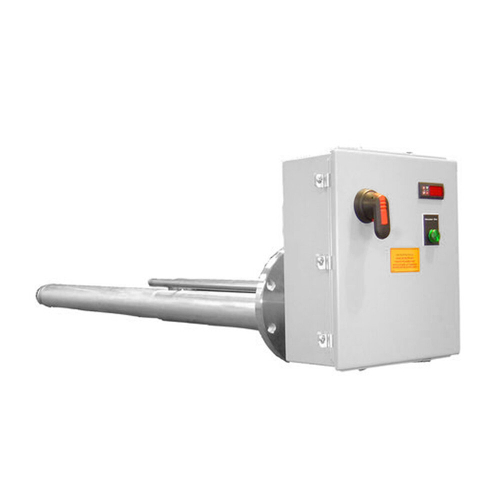
Other electric heating elements serve different heat-transfer tasks. A Single-sided heating rod, for example, uses a single-ended connection and is used to heat molds or other metal parts that transfer heat; some configurations are intended for outdoor or immersion applications. Its application is distinct from a cable distributed along insulated pipework, and suitability for any particular fluid or environment requires confirmation.
Finding a fault before a pipe freezes
A pipe that feels cold does not by itself identify the fault. The controller may be calling for no heat, the circuit may have lost power, a protective device may have tripped, or a cable or connection may be damaged. A cold area confined to a valve can point toward local heat loss or missing insulation rather than failure of the entire circuit.
Inspection is most useful when the electrical and thermal sides are considered together. Records of circuit identification, insulation resistance tests, controller settings, and repairs provide a reference for comparison. Testing must follow the equipment instructions and appropriate electrical safety procedures; a satisfactory electrical reading alone does not prove that every fitting has adequate insulation or cable coverage.
After pipe repairs, the trace cable, sensor, and insulation need to be restored to their intended positions. A displaced sensor or an insulation cover left open can undermine an otherwise functional heating circuit. Where a process cannot tolerate freezing during a power interruption, heat tracing also needs a plan for loss of supply, since an unpowered cable cannot replace escaping heat.
News list
- Where can an LNG electric heater be used in a vaporization system?Nov 05, 2026
- Choosing an industrial immersion heater for a corrosive liquidNov 05, 2026
- How electrical heat tracing protects pipes from freezingNov 05, 2026
- Hazardous area classification for sulfur recovery explosion-proof electric heatersNov 05, 2026
- How to identify a replacement for a Chromalox tubular heaterNov 05, 2026
- Understanding Industrial Electric Heaters: Operating Principles and Process UsesSep 15, 2026
Send us a message